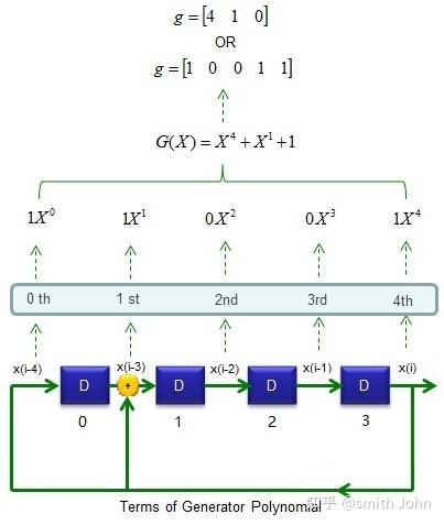
It is clear that the unrolled representation of the LFSR is much more readable, but the implementation is the same as clear in FIGURE where it is reported the output of the layout of the two VHDL code of LFSR implemented above.įigure 3 – ModelSim VHDL RTL simulation of LFSR implementation R_lfsr <= '0'&r_lfsr(G_M downto 2) xor w_mask Signal r_lfsr : std_logic_vector (7 downto 1) O_lsfr : out std_logic_vector (6 downto 0)) I_seed : in std_logic_vector (6 downto 0) Starting from the generic LFSR structure, the VHDL Galois implementation is straightforward as in Figure 2: Figure 2 – 7-bit Galois implementation of an LFSR library ieee In Figure 2 is reported a 7-bit LFSR using the generator polynomial

The VHDL implementation of an LFSR is very simple starting from its graphical representation. In this post, we focus on Galois LFSR architecture, all the consideration can be ported to the Fibonacci architecture. The LFSR can be implemented also using XNOR primitive function instead of XOR. Vice versa we can use the Fibonacci implementation in the modern FPGA taking advantage of the LUT architecture that can implement the XOR matrix as multiport XOR function. In the Fibonacci implementation, the XOR ports are cascaded so in this case, the delay due to the consecutive ports can affect the timing performances of the circuit. If we are implementing the LFSR in hardware, the Galois implementation is much more efficient since use two input XOR function and the XOR function is implemented between two consecutive registers.

There are two different types of LFSR implementation the FIBONACCI and the GALOIS implementation as in Figure1. We can use this type of functions in many application such as counters, crypto, ber-meter, CRC generation, scrambling/descrambling algorithm, test application and so onĪn LFSR of length N can generate 2^N-1 different states where the values look like pseudo-random values.

A linear-feedback shift register (LFSR) is a shift register whose input bit is a linear function of its previous state.


 0 kommentar(er)
